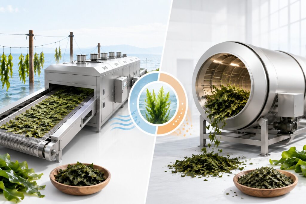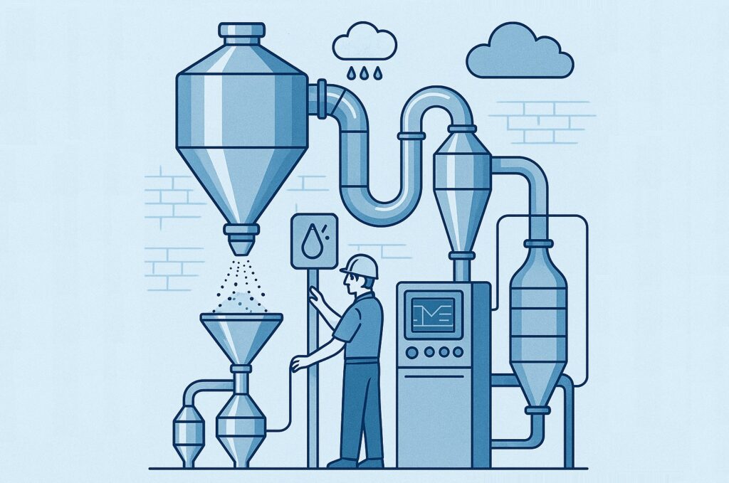


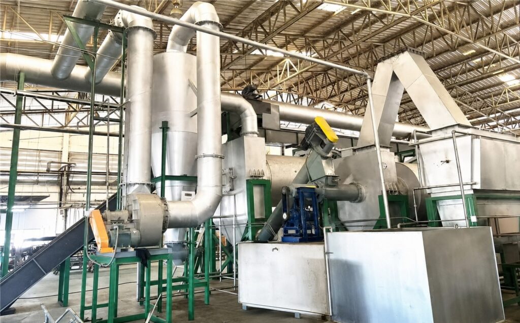
How Industrial Decarbonization Strategies Impact Process Performance and Product Quality
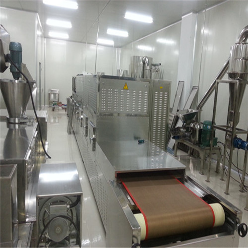
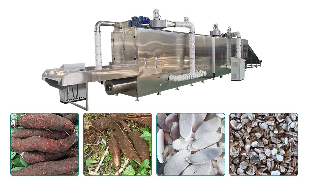
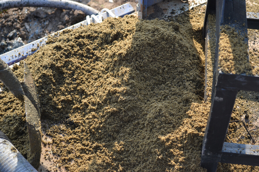
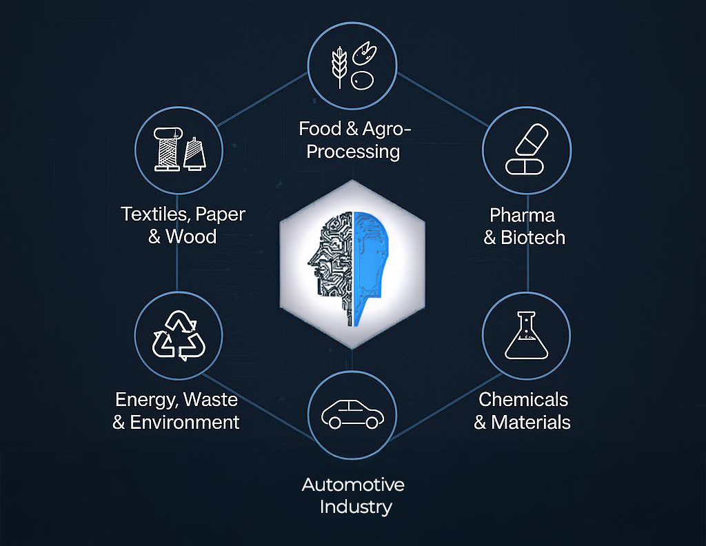
Industrial decarbonization is no longer a future concept; it is a practical engineering strategy for reducing emissions while maintaining output, efficiency, and product consistency. In drying, dehydration, sludge treatment, biomass handling, and thermal processing, the real challenge is not just cutting carbon. It is doing so without damaging throughput, moisture targets, texture, colour, hygiene, or […]